|
ORDER PATHS
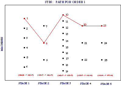
The flow of material in the plant can be mapped. Figure 3 illustrates the optimal path for order 1 for the example problem with 5 orders in 650 hours of operation.
The number above the points indicate the unit in which the task is processed and the numbers in the paranthesis are the starting and ending times in each processing stage.
Order 1 is processed in the following sequence: units 1-8-10-20-23.

|

